LOCK
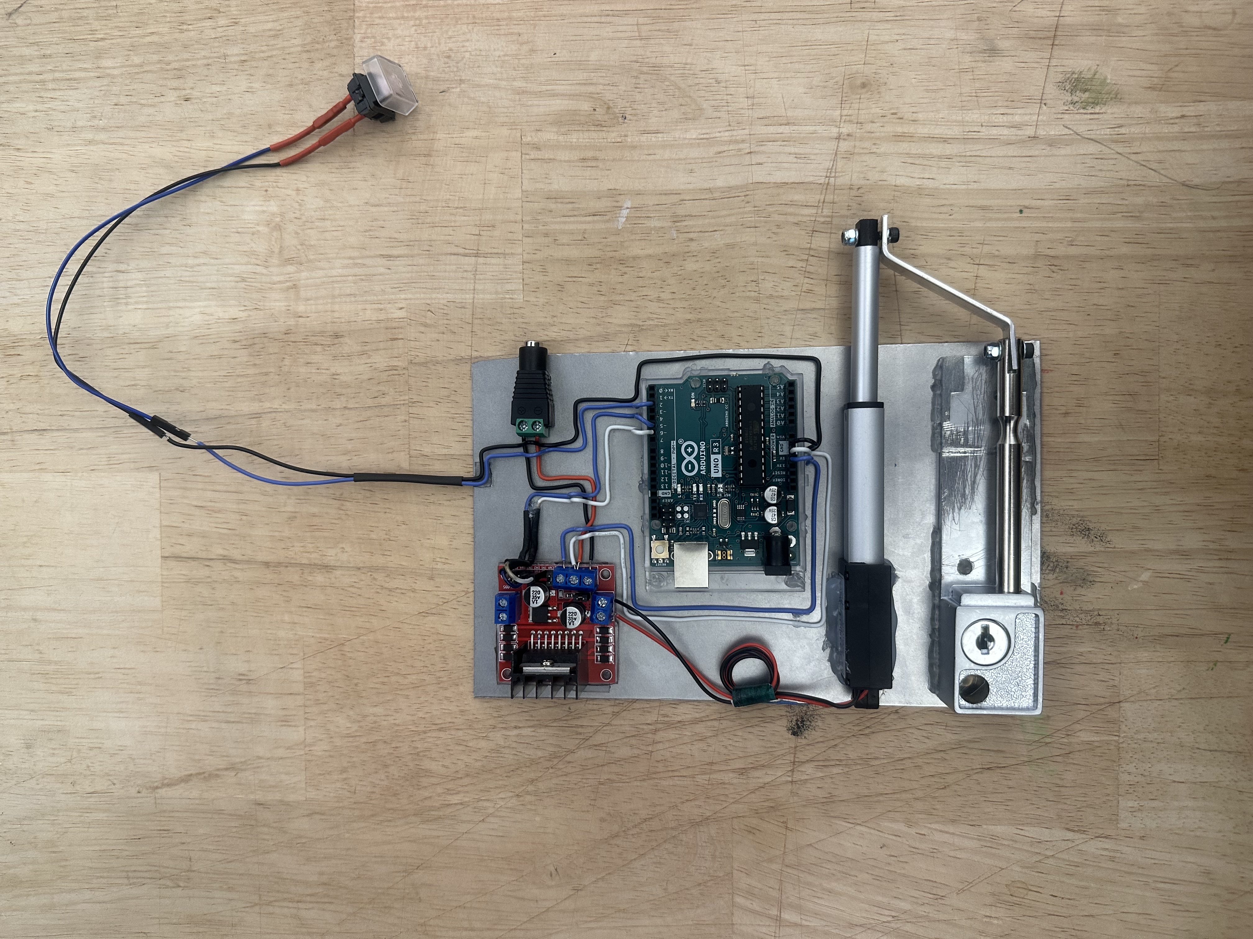
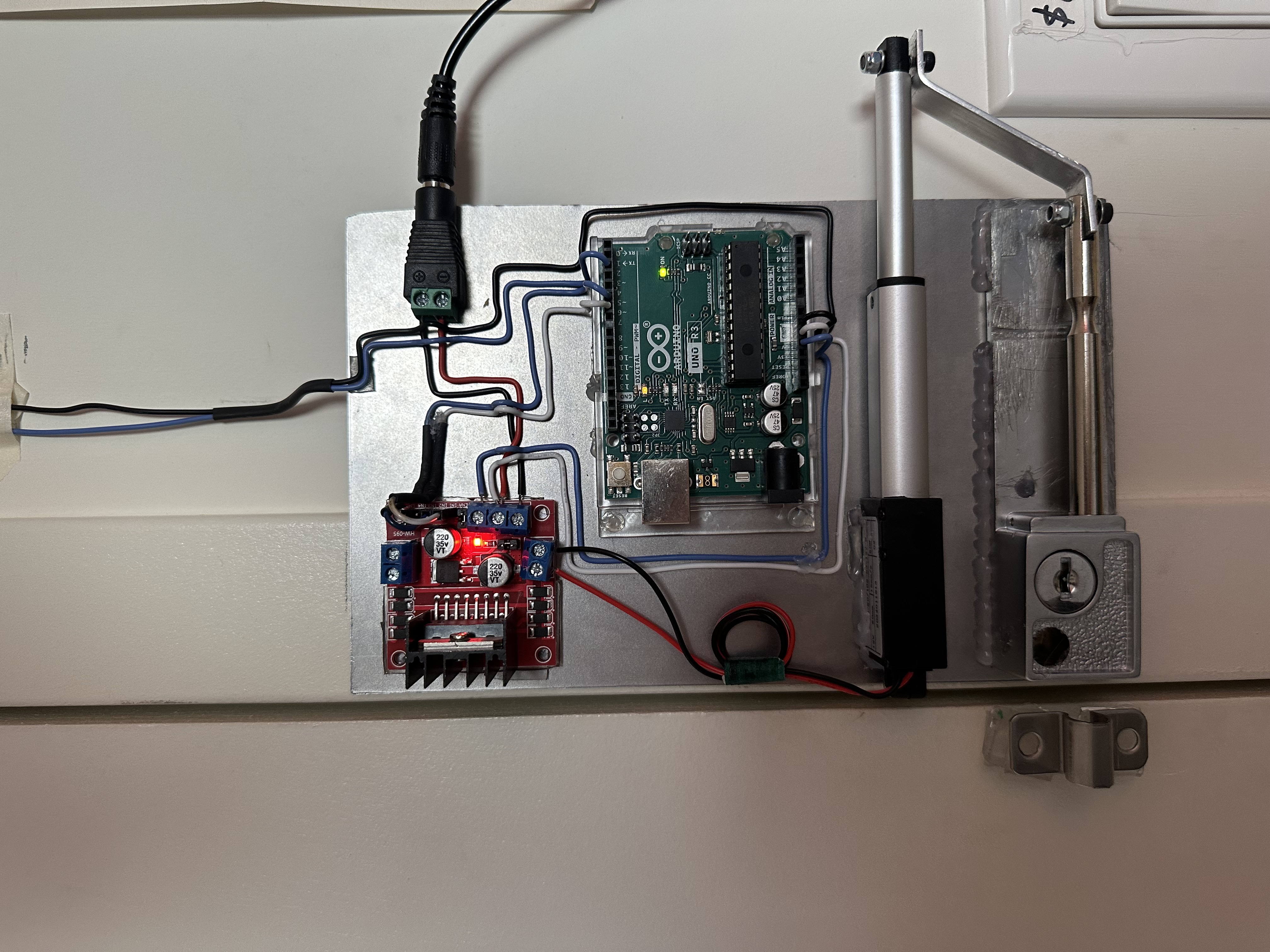
A motorized door lock with every part left on display. Press the wired button and an Arduino Uno drives a 12V linear actuator through an L298N motor driver. The actuator pushes a lever I cut from aluminum, and the lever slides the bolt of a keyed barrel lock. It's all mounted on one metal plate on my bedroom door.
The brief
The assignment was to design for a dystopia of any kind. I looked at a world where security is heavily monitored: every lock is connected, and every door reports back to someone you can't see.
My answer was a lock that hides nothing. It's analog and a little vintage, and you can watch it work. The circuit, the motor driver and the actuator are all mounted in the open, so you can follow exactly what happens when the button is pressed.
Smart locks ask you to trust what's inside a sealed box. This one has no box, so there's nothing to take on trust. It was also my chance to learn Arduino properly: writing the code, and driving a motor that needs more power than the board can supply on its own.
Build
Plate
Everything mounts to a single metal plate. The barrel lock sits at the bottom, with the actuator above it, and the boards above that.
Lever
I cut, bent and drilled a strip of aluminum into a lever that links the actuator's rod to the bolt. When the rod extends or retracts, the bolt slides with it.
Wiring
The wires on the plate are routed by hand in straight runs, so the electronics read as part of the design instead of a mess to hide.
Button
My teacher suggested pushing the exposed look further, so the push button runs off on a very long wire instead of being built in.
How it moves
PRESS
The wired button tells the Arduino Uno to move.
PUSH
The L298N switches 12V and the actuator extends or pulls back.
SLIDE
The aluminum lever carries that motion to the bolt.
Circuit
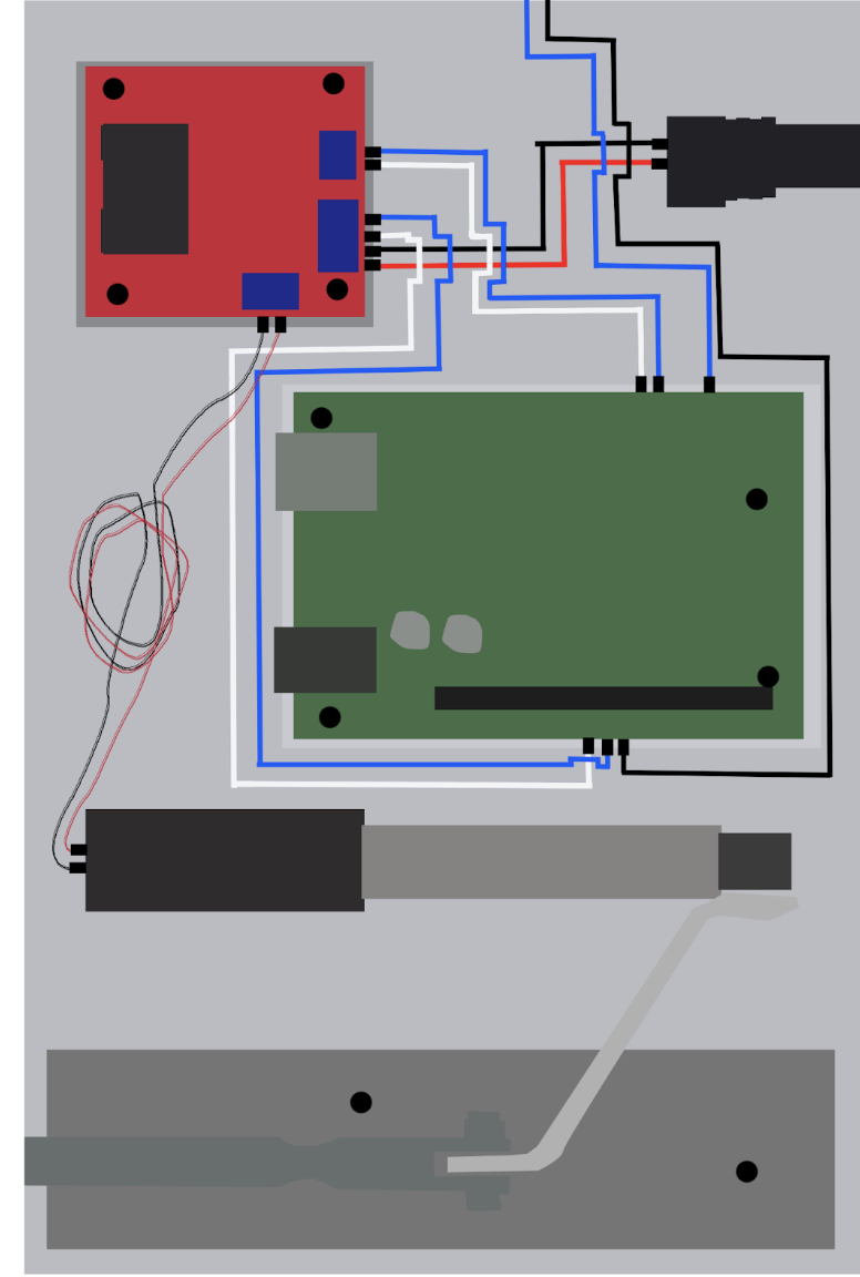
The Arduino can't power a 12V actuator by itself, so it goes through an L298N motor driver. One 12V jack feeds the driver. When the button is pressed, the Arduino reads it and sends a direction signal to the driver, and the driver switches the 12V supply to push the actuator out or pull it back in.
- Power
- 12V jack → L298N motor driver → linear actuator
- Control
- Push button → Arduino Uno → L298N direction inputs
Learned
This project taught me Arduino programming, how to control a motor safely through a driver, and how to fabricate a part like the lever and make it line up with a real lock. It also showed me how much of a project's meaning comes from what you choose to show.
Next, not built yet: Next, I'd like to replace the wired button with a Bluetooth connection. I haven't built that yet. The hard part would be keeping a wireless version as easy to understand as the wired one.